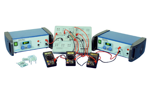
Transistors Characterstics

Item Code: SJ251

Principle and Working:

Diode : It is a device formed from a junction of n-type and p-type semiconductor material. In the forward-biased and reversed-biased regions, the current and the voltage, of a semiconductor diode are related by the diode equation:
I = I0(ev/ηvt-1)
Where I = current flowing in the diode,
I0 = reverse saturation current
V = voltage applied to the diode,
Vt = volt- equivalent of temperature = k T/q = T/ 11,600 = 26mV (@ room temp)
... Transistor : It is a semiconductor device used to amplify or switch electrical signals and power. The I-V characteristics of a transistor refer to the relationship between the current flowing through the transistor and voltage applied across it. These characteristics differ from different transistor configurations namely the common emitter, common base, and common collector configurations.
Field-Effect Transistor (FET): It Also known as Unipolar Transistor, is a three-ended (three electrodes), voltage-controlled semiconductor electronic component that can amplify the electrical signal. It is used to study Output / drain characteristic and Transfer characteristics:


  • Diode characteristics of transistor junctions.
  • To study the characteristics of a transistor.
  • To study the characteristics of a field-effect transistor.
  • Students use plug-in modules for circuit design.
  • Component mounted on PCB and these PCB fix in a transparent housing for the visibility of the components.
  • The symbol's name and the value of the components are printed on top of the transparent housing.
  • Convenient & Easy to make circuit diagram using plug-in modules.
  • Do it yourself approach provodeds better learning.
  • Economical & Flexible method of performing all experiments on one circuit board.

    Regulated Power Supply

  • Regulated Power Supply : Output Voltage 0 -16V, 1 Amp, 5V. 1 Amp. DC Fixed
  • Ripple Less than 25mV
  • Display 3 1/2 Digit LED for 0-16V DC
  • Input voltage 230V AC, 50 Hz
  • Digital Multimeter

  • Resistance :200W, 2000W, 20k, 200k & 2000k W.
  • D.C.Voltage : 200 & 2000 mV 20V, 200V & 600 V
  • A.C.Voltage : 200 & 600 V
  • D.C.Current : 200 & 2000 micro A, 20mA & 200 mA, 10A
  • Testing : Diode & transistor
  • Battery : 9V
  • Plug-in Modules

  • 2/ 4 pin modules, 4mm plug-in pins, transperent cover, Symbol/Circuit printed on cover.
  • Plug-in Board

  • Plug-in board has 4mm sockets, arranged in 2 x 2 matrix. Total matrix 24nos.

  • 1 Circuit Board
  • 3 Digital Multimeter
  • 6 Flexible Lead Set (50cm)
  • 4 Flexible lead Set (100cm)
  • 1 Resistor Module 1kΩ
  • 1 Resistor Module 10kΩ
  • 1 Resistor Module 100kΩ
  • 1 Transistor Module 2N2222
  • 1 JFET Module
  • 1 Diode Module
  • 2 Variable Power Supply