Opamp As Oscillator

Item Code: SJ258

Principle and Working:

To study RC phase shift oscillator using Op-Amp
A RC phase shift oscillator is a type of oscillator circuit that uses a combination of resistors (R) and capacitors (C) in a feedback network to generate a sine wave output. The principle behind the RC phase shift oscillator is that a feedback network consisting of resistors and capacitors introduces a phase shift to the input signal. The stability and amplitude of the oscillations in an RC phase shift oscillator can be affected by various factors, such as component tolerances, temperature variations, and loading effects.
... To study wien bridge oscillator using Op-Amp A Wien bridge oscillator is a type of oscillator circuit that uses a bridge network of resistors and capacitors along with an operational amplifier (Op-Amp) to generate a sinusoidal output waveform at a specific frequency. The working principle of a Wien bridge oscillator using an Op-Amp it consists of a bridge network that includes two resistors (R1 and R2) and two capacitors (C1 and C2) connected in a specific configuration. The bridge network is often designed in the form of a Wheatstone bridge, with one of the diagonals containing the resistors and capacitors.
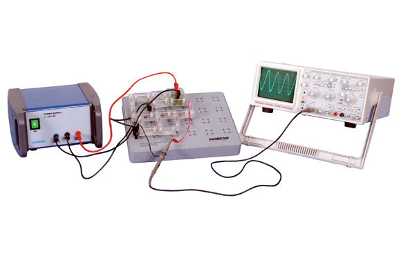


  • To Study RC Phase Shift Oscillator Using Op-Amp.
  • To Study Wein Bridge Oscillator Using Op-Amp.
  • Students use plug-in modules for circuit design.
  • Component mounted on PCB and these PCB fix in a transparent housing for the visibility of the components.
  • The symbol's name and the value of the components are printed on top of the transparent housing.
  • Convenient & Easy to make circuit diagram using plug-in modules.
  • Do it yourself approach provodeds better learning.
  • Economical & Flexible method of performing all experiments on one circuit board.

    Power Supply

  • Power Supply : Output voltage ±15V Fixed, Current 500mA
  • Overload protection Current limiting.
  • Input Voltage 230V AC, 50Hz
  • Plug-in Modules

  • 2/ 4 pin modules, 4mm plug-in pins, transperent cover, Symbol/Circuit printed on cover.
  • Plug-in Board

  • Plug-in board has 4mm sockets, arranged in 2 x 2 matrix. Total matrix 24nos.

  • Note: CRO/DSO not supplied with this setup.

  • 1 Circuit Board
  • 1 Power Supply +/- 15V
  • 6 Flexible Lead Set (25cm)
  • 4 Flexible Lead Set (50cm)
  • 3 Flexible lead Set (100cm)
  • 1 OP-AMP Module
  • 3 Resistor Module 3.3kΩ
  • 3 Resistor Module 10kΩ
  • 2 Resistor Module 15kΩ
  • 2 Resistor Module 27kΩ
  • 1 Resistor Module 100kΩ
  • 1 Variable Resistor 1MΩ
  • 3 Capacitor Module 0.01µF
  • 2 Capacitor Module 0.022µF
  • 3 Capacitor Module 0.1µF
  • 1 CRO 20 MHz (Optional)