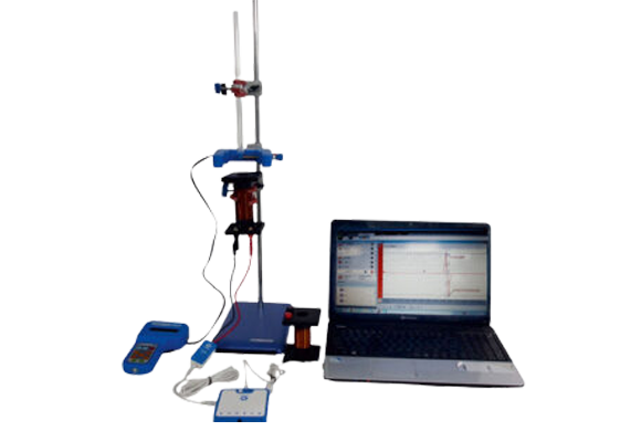
Faraday’s law & induced e.m.f

Item Code: SED1003

Principle and Working:

An induced e.m.f. (or induced current) is produced across a conductor when it is exposed to a change in a magnetic field. The mathematical law that relates the changing magnetic field to the induced current (or the induced voltage) is called Faraday's Law.
... Lenz’s law describes the magnetic flux through the circuit and gives the direction of the induced e.m.f. This gives rise to induced current which opposes the change in magnetic flux .
In the present setup, a permanent magnet falls with different velocities through a coil. The change in the magnetic flux generates an induced voltage impulse. The induced voltage impulse is recorded with voltage probe through Data Logger. Depending on the polarity of the permanent magnet the induced voltage impulse is negative or positive.


  • Data logger with 100k samples per second capacity.
  • coils with different turns (700 & 1150) and gauge (30 & 26).
  • Free data analyzing software.
  • Digital Timer with navigation keys to work in different modes (Time, Velocity, Acceleration, mask and counter)

  • Verification of Faraday and Lenz’s law of induction by measuring the induced voltage as function of time.
  • Measurement of the induced voltage impulse as a function of the velocity of the magnet.
  • Calculation of the magnetic flux induced by the falling magnet as a function of the velocity of the magnet.
  • Dataloger : Up to 100K SPS, memory capacity 800K sample, Li polymer rechargeable battery, 6 in-built sensor, 4 ext. sensor port (60+ sensor available), connectivity port micro USB, 90.2 x 90.2 x 20mm(LxWxH), 120gm
  • Voltage Sensor : ± 2.5V (AC/DC), accuracy ± 3%, resolution 1.25mV, input resistance > 1MΩ
  • Digital Timer : 2 line LCD display, resolution 0.1 ms, Mode Time, Speed & Acceleration, USB interface, 5V DC operating voltage
  • Photogate : Detector Infra red, RJ11 connector
  • Coils :SWG 30 & 26, L(mm) 75 & 100, turns 700 & 1150, R(Ω) 19 & 13.5, L(mH) 13.8 & 8.8, I(A)max 0.3 & 0.7
  • Magnet : Cylindrical, Size 50x10mm (LxΦ), Alnico
  • 1 Data Logger
  • 1 Voltage Sensor
  • 1 Support Base & 1 Support Rod
  • 1 Three Fingle Clamp
  • 3 Bosshead
  • 1 Coil N = 700, L = 75mm, Dia = 32mm
  • 1 Coil N = 1150, L = 75mm, Dia = 32mm
  • 1 Cylindrical Magnet
  • 1 Tube 300mm
  • 1 Digital Timer with adapter
  • 1 Photogate
  • 1 Software CD
  • 1 Burette Clamp
  • 1 Sensor cable (mini USB)