Electronic Plug In Kit

Item Code: SK023

Principle and Working:

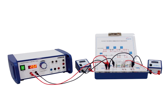
Electronics kit is a complete solution for student to get the knowledge of analog and digital electronics. this kit has 52 verified experiments. This kit includes different electronics modules (Components), 2 signal generator and 3 power supplies.Like diode, transistor, 555 timer, Op- amp and Digital gates etc. All the modules are plug in modules. Student will do the experiment by their own.


  • Students use plug-in modules for circuit design.
  • Component mounted on PCB and these PCB fix in a transparent housing for the clear visibility of the components.
  • The symbol's name and the value of the components are printed on top of the transparent housing.
  • Convenient & Easy to make circuit diagram using plug-in modules.
  • Do it yourself approach provodeds better learning.
  • Economical & Flexible method of performing all experiments on one circuit board.

  • Recording the I-V & I-R characteristics of solar cell.
  • Diode characteristics of transistor junctions.
  • Recording the characteristics of a transistor.
  • Recording the characteristics of a field-effect transistor.
  • To study half wave and full wave (bridge) rectifier.
  • To study capacitor filter effect in power supply.
  • To study unregulated and regulated power supply.
  • To study CE amplifier frequency response.
  • To study RC-coupled amplifier (multistage amplifier).
  • To study differential amplifier circuits.
  • To study Astable multivibrator circuit using transistor.
  • To study Colpitt’s oscillator.
  • To study Hartley oscillator.
  • To study UJT as relaxation oscillator.
  • To study half adder and full adder circuit.
  • To study half Subtractor.
  • To study BCD to 7-segment decoder using 7segment display.
  • To study decade counter.
  • To study RS flip flop.
  • To study D flip flop.
  • To study JK flip flop.
  • To study shift registers
  • Recording the current-voltage characteristics of diodes.
  • Recording the current-voltage characteristics of zener diodes.
  • Recording the current-voltage characteristics of LED.
  • AND, OR, XOR, NOT, NAND and NOR operations.
  • De Morgan’s laws.
  • Logic operation using three and four variables.
  • To Study RC Phase Shift Oscillator Using Op-Amp.
  • To Study Wein Bridge Oscillator Using Op-Amp.
  • To Study Astable Generators Using IC555 Timer.
  • To Study Monostable Generators Using IC555 Timer.
  • Op-Amp as Inverting/Non Inverting Amplifier.
  • Op-Amp as Adder/Subtractor.
  • Op-Amp as Integrator/ Differentiator.
  • Op-Amp as a Comparator.
  • To study MOSFET characteristics.
  • To study characteristics of SCR.
  • To study characteristics of TRIAC.
  • To Study Ohm’s Law.
  • To Study Kirchoff’s Law.
  • To Study Series & Parallel Effect of Resistance.
  • To Study Resistances As A Voltage Divider.
  • To Study LDR Characteristics.
  • To Study Thermistor Characteristics.
  • To study ADC/DAC circuits.
  • To study the R-C Circuit.
  • To study the L-R Circuit.
  • To study the L-C-R Circuit.
  • To study the Clipper and Clamper Circuit.
  • To study the Charging and Discharging of a Capacitor.

  • Power Supply : Output voltage 0 – ±15V DC, ON/OFF switch, fuse 1A, 4 rubber feet.
  • Power Supply : Output voltage 0 – 20V, 5V DC, 1A, ON/OFF switch, fuse 1A, 4 rubber feet, Thermal safety switch for 5V DC.
  • Signal Generator : Output range 1Hz – 110kHz in four decade ranges, Variable Voltage from 0 to 10V (V ). PP, Waveform sine & square, Current rating directly drives the load less than 1Amp.
  • Circuit Board : 4 mm safety socket, dimension 305 x 245 x 62mm, plastic mold, 4 rubber feet, templates holder with clamp.
  • Modules : Transparent module with 2 & 4 legs, 4mm safety plugs, Module name, Symbol and circuit printed on top.
    • 1 ADC Module 1 AND Gate Module
    • 2 AND Gate Module (Single Gate)
    • 1 BRIDGE Rectifier Module
    • 2 Capacitor Module 0.001μF
    • 3 Capacitor Module 0.01μF
    • 2 Capacitor Module 0.022μF
    • 2 Capacitor Module 0.047μF
    • 3 Capacitor Module 0.1μF
    • 3 Capacitor Module 0.47μF
    • 3 Capacitor Module 10μF
    • 1 Capacitor Module 100μF
    • 1 Capacitor Module 1000μF
    • 1 Choke Module
    • 1 Circuit Board
    • 1 D-Flip Flop
    • 1 DAC Module
    • 1 Decade Counter Module
    • 1 Decade Resistance Box
    • 3 Digital Multimeter
    • 1 Diode Module
    • 2 Ex-OR Gate Module
    • 2 Ex-OR Gate Module (Single Gate)
    • 1 Fixed Power Supply +/- 15 V
    • 6 Flexible Lead Set (25cm)
    • 8 Flexible Lead Set (50cm)
    • 5 Flexible lead Set (100cm)
    • 1 FND+7 Segment Decoder
    • 1 Full Adder Module
    • 1 Half Adder Module
    • 1 Half Substractor Module
    • 1 IC555 timer Module
    • 2 Inductor Module 30mH
    • 1 Inductor Module 60mH
    • 1 JFET Module
    • 1 JK Flip Flop Module
    • 1 LAMP Source
    • 1 LED Module
    • 1 Light Sensor (LDR) Module
    • 1 MOSFET Module
    • 1 NAND Gate Module
    • 1 NAND Gate Module (Single Gate)
    • 1 NOR Gate Module
    • 1 NOR Gate Module (Single Gate)
    • 1 NOT Gate Module
    • 2 NOT Gate Module (Single Gate)
    • 1 OP-AMP Module
    • 1 OR Gate Module
    • 1 OR Gate Module (Single Gate)
    • 1 Push Button Module
    • 1 Regulator Module
    • 1 Resistor Module 100Ω
    • 1 Resistor Module 330Ω
    • 2 Resistor Module 1kΩ
    • 3 Resistor Module 3.3kΩ
    • 1 Resistor Module 4.7kΩ
    • 5 Resistor Module 10kΩ
    • 2 Resistor Module 15kΩ
    • 2 Resistor Module 27kΩ
    • 2 Resistor Module 33kΩ
    • 1 Resistor Module 75kΩ
    • 1 Resistor Module 100kΩ
    • 1 Resistor Module 330kΩ
    • 1 Resistor Module 470kΩ
    • 1 Resistor Module 1kΩ, 1W
    • 1 Resistor Module 100Ω, 1W
    • 2 Resistor Module 50Ω, 1W
    • 1 RS Flip Flop
    • 1 SCR Module
    • 1 Shift Register Module
    • 2 Signal Generator
    • 1 Solar Module
    • 2 Switch Module
    • 1 Thermistor Module
    • 1 Transformer Module
    • 2 Transistor Module 2N2222
    • 2 Transistor Module BC107
    • 2 Transistor Module BC109
    • 1 Triac Module
    • 1 UJT Module
    • 2 Variable Power Supply
    • 1 Variable Resistor 1kΩ
    • 1 Variable Resistor 10kΩ
    • 1 Variable Resistor 1MΩ
    • 1 Zener Diode Module
    • Ohm’s law
    • Charging and discharging
    • Rectifier circuits.
    • LED & Zener diode characteristics.
    • Clipper and clamper circuit.
    • Transistor characteristics.
    • Analog & digital circuits.
    • Logic gates & Flip-flops.
    • Amplifiers & oscillators.
    • Transistor & Op-Amp.