

Principle and Working:
DIODE
The working principle of a diode is based on its semiconductor properties, specifically the formation of a junction between two different types of semiconductor materials: P-type (positive or holes) and N-type (negative or electrons). This junction is called a PN junction. Diode has two operations: region forward and reverse bias region based on the external power supply.
● Forward Bias Region: When the diode is forward-biased.the diode allows current to flow easily. In this region, the diode exhibits very low resistance.
● Reverse Bias Region: When the diode is reverse-biased.The diode blocks the current flow. In this region, the diode acts as an open circuit, and only a very small reverse leakage current flows.
...
ZENER DIODE
A Zener diode is a specialized type of diode that is designed to operate in reverse-biased breakdown mode.When connected to forward bias its characteristics are just like a normal diode.In reverse bias conditions, the Zener diode blocks the flow of current until the reverse breakdown voltage is reached. and starts conducting in the reverse direction that voltage at which breakdown happens is called the Zener voltage.
LED
LED (Light-Emitting Diode) : Light-emitting diodes are heavily doped p-n junctions. When a forward voltage is applied across the p-n junction of the LED. the excess electrons from the n-region and the excess holes from the p-region begin to move towards each other and recombine at the junction. This recombination process releases energy in the form of photons, which are particles of the light wavelength of the emitted light depending on the bandgap energy of the semiconductor material used in LEDs.
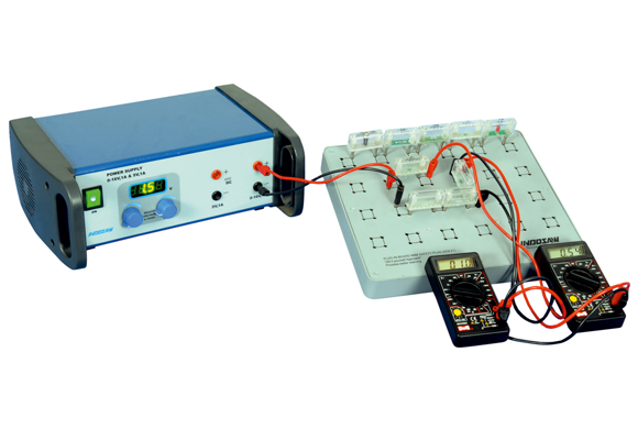
Regulated Power Supply
Plug-in Modules
Plug-in Board