Diode Circuit And Power Supply

Item Code: SJ252

Principle and Working:

In half wave rectification, either the positive or negative half of the AC wave is passed, while the other half is blocked.
A full-wave rectifier converts the whole of the input waveform to one of constant polarity (positive or negative) at its output.
The filter capacitor refers to an energy storage device installed at both ends of the rectifier circuit to reduce the ripple coefficient of AC pulsation and improve the efficient and smooth DC output.
... A regulated power supply is an electronic circuit that is designed to produce a constant DC power supply or voltage that is independent of the current drawn from the temperature on the top of any variations in the AC line voltage.
An unregulated power supply is the one that provides a predetermined output based on the input and load voltage and even a little variation in the input directly affects the output voltage.
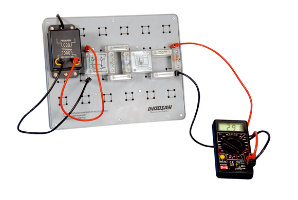


  • To study half wave and full wave rectifier.
  • To study full wave (bridge) rectifier.
  • To study capacitor filter effect in power supply.
  • To study unregulated and regulated power supply.
  • Students use plug-in modules for circuit design.
  • Component mounted on PCB and these PCB fix in a transparent housing for the visibility of the components.
  • The symbol's name and the value of the components are printed on top of the transparent housing.
  • Convenient & Easy to make circuit diagram using plug-in modules.
  • Do it yourself approach provodeds better learning.
  • Economical & Flexible method of performing all experiments on one circuit board.

    Transformer

  • Center tapped 9-0-9V AC
  • Copper Winding
  • Digital Multimeter

  • Resistance :200W, 2000W, 20k, 200k & 2000k W.
  • D.C.Voltage : 200 & 2000 mV 20V, 200V & 600 V
  • A.C.Voltage : 200 & 600 V
  • D.C.Current : 200 & 2000 micro A, 20mA & 200 mA, 10A
  • Testing : Diode & transistor
  • Battery : 9V
  • Plug-in Modules

  • 2/ 4 pin modules, 4mm plug-in pins, transperent cover, Symbol/Circuit printed on cover.
  • Plug-in Board

  • Plug-in board has 4mm sockets, arranged in 2 x 2 matrix. Total matrix 24nos.

  • 1 Circuit Board
  • 1 BRIDGE Rectifier Module
  • 1 Capacitor Module 10 µF
  • 1 Capacitor Module 100 µF
  • 1 Capacitor Module 1000 µF
  • 2 Digital Multimeter
  • 2 Diode Module
  • 4 Flexible Lead Set (25cm)
  • 6 Flexible Lead Set (50cm)
  • 1 Resistor Module 330Ω
  • 1 Resistor Module 1kΩ
  • 1 LED Module
  • 1 Regulator Module
  • 1 Transformer Module
  • 1 CRO 20 MHz (Optional)